
IP Address
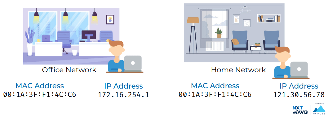
IP addresses belong to the networks, not the devices attached to those networks.
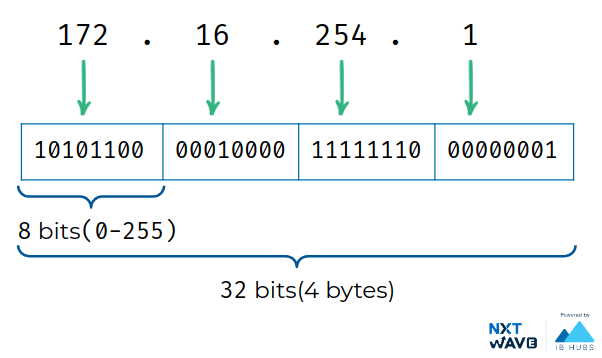
Example: 172.16.254.1
IPv4 Addressing
IP addresses are a 32 bit long numbers made up of four octets,
each octet is normally described in decimal numbers.
8 bits of data or a single octet can represent all decimal numbers from 0 to 255. This format is known as dotted decimal notation.
232 = 4 x 10⁹ Possible IPs
IPv6 Addressing
IPv6 IP addresses are a 128 bit long numbers made up of eight groups of four hexadecimal digits,
each group representing 16 bits

IP addresses belong to the networks, not the devices attached to those networks.your laptop will always have the same MAC address no matter where you use it, but it will have a different IP address assigned to it at an office than it would when you're at home. The LAN at the office, or the LAN at your house would each be individually responsible for handing out an IP address to your laptop if you power it on there.
Router
Forward data between independent networks.
Store route information for different networks all over the world.
Network Layer device

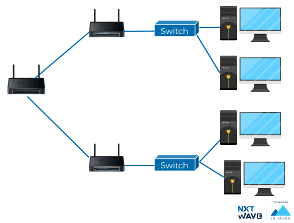
Wireless Router
Wireless Routers are combination of
Router
Switch
Wireless Access Point
Wireless Access Point
Wireless access point (WAP): Allows other Wi-Fi devices to connect to a wired network.
Router
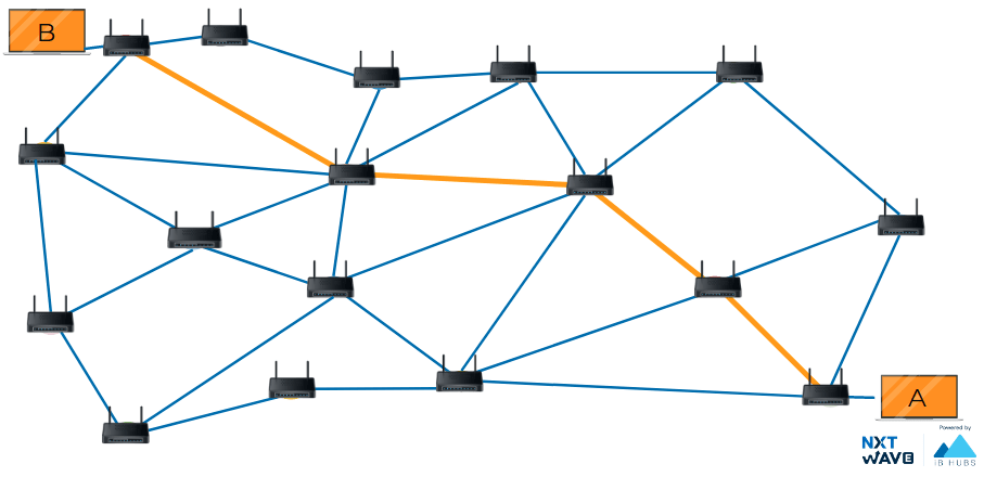
Network of Networks

Route
The sequence of communication links and packet switches traversed by a packet from the sending end system to the receiving end system is known as a route or path.
The routers are constantly trying to balance the load across whataevere routes they know to ensure speedy and reliable delivery which is conjunction control.
Subnetting
Subnetting is the process of splitting a large network into many smaller sub-networks or subnets
Network Efficiency
Security
Easier Management
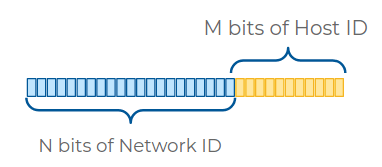
Subnetting IP Address
Network ID: Used to identify the network.
Host ID: Used to identify individual hosts in the network.
Subnet Mask is used to identify the network ID and Host ID
| IP Address | 223 | 1 | 1 | 2 |
|---|---|---|---|---|
| IP Address (Binary) | 11011111 | 00000001 | 00000001 | 00000010 |
| Subnet Mask (Binary) | 11111111 | 11111111 | 11111111 | 00000000 |
| Subnet Mask | 255 | 255 | 255 | 0 |
CIDR Notation
The slash notation (a.b.c.d/x) is also known as CIDR notation. It can represent an IP and a subnet mask.
| CIDR | 223.1.1.2/23 |
|---|---|
| IP Address | 223.1.1.2 |
| Subnet mask | 255.255.254.0 |
- The entire IP and subnet mask can be written now as 223.1.1.2/24
- /24 notation represents no of ones in subnet mask.
- We know that the octet available for host IDs can contain the numbers 0-255, but zero is generally not used and 255 is normally reserved as a broadcast address for the subnet. This means that, really, only the numbers 1-254 are available for assignment to a host.
| CIDR | IP Address in Binary | IP address Range | Possible Hosts | |||
|---|---|---|---|---|---|---|
| 223.1.1.0/24 | 11011111 | 00000001 | 00000001 | 00000000 | 223.1.1.0 to223.1.1.255 | 254 |
| 223.2.1.0/23 | 11011111 | 00000010 | 00000001 | 00000000 | 223.2.0.0 to223.2.1.255 | 510 |
| 223.3.1.0/22 | 11011111 | 00000011 | 00000001 | 00000000 | 223.3.0.0 to223.3.3.255 | 1022 |
*First address in the network is reserved for the network.
*Last address in the network would be reserved for broadcasting.

Forwarding
Basic routing has just a few steps
a router receives a packet of data on one of its interfaces
the router examines the destination IP of this packet.
the router then looks up the destination network of this IP in its routing table.
the router forwards that out though the interface that's closest to the remote network. As determined by additional info within the routing table.
These steps are repeated as often as needed until the traffic reaches its destination.

Routing Table
Router maintain a routing table which contain the information about where to forward the incoming packet.
| Destination | Next Hop |
|---|---|
| 9.1.1.0/24 | 172.16.5.10 |
| 223.1.1.0/24 | 172.16.5.11 |
| 64.0.10.0/24 | 172.16.5.12 |
| * | 172.16.5.10 |
Destination Network: Row for each network that the router knows about. Network ID and Net Mask.
Next Hop: Next router that data should be forwarded.
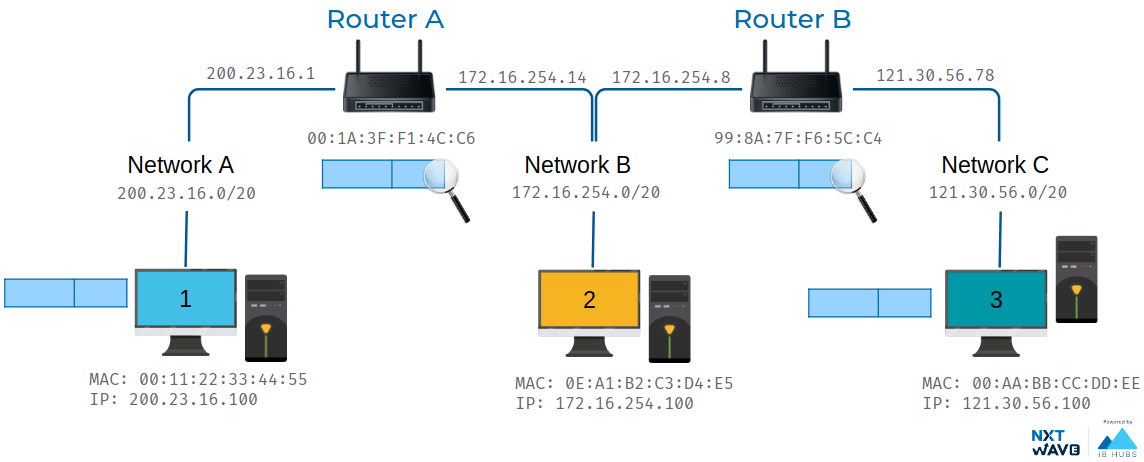
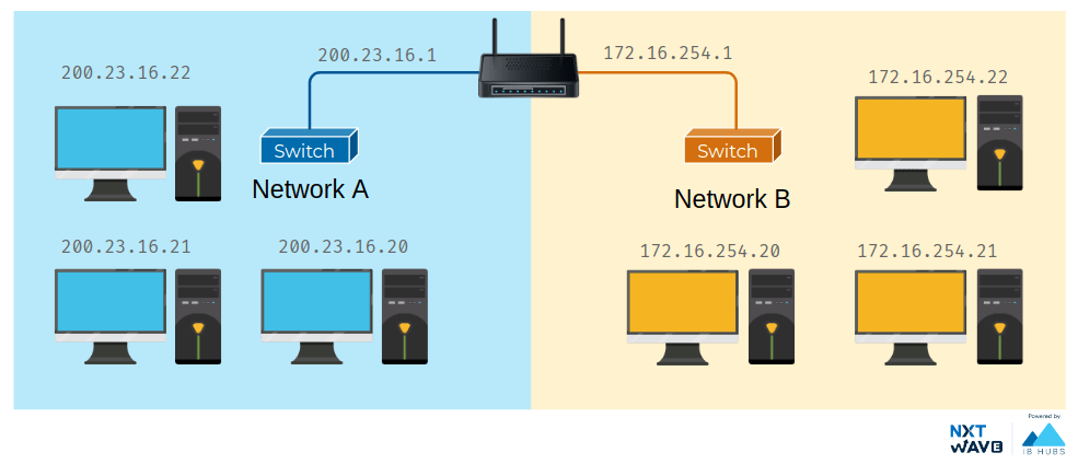
Example consider three network that data need to be sent data from computer on network A to computer on network c.the third Network C has an address space of 172.16.1.0/23. There is a second router connecting network B and network C. It's interface on network B has an IP of 172.16.254.8 and its interface on Network C has an IP of 121.30.56.78.
The computer at 200.23.16.100 knows that 121.30.56.100 is not on its local network, so it sends a packet to its gateway, the router between Network A and Network B. Again, the router inspects the content of this packet. It sees a destination address of 121.30.56.100 and through a lookup of its routing table, it knows that the quickest way to get to the 121.30.56.0/20 network is via another router. With an IP of 121.30.56.100 The router decrements the TTL field and sends it along to the router of 172.16.254.8. This router then goes through the motions, knows that the destination IP of 121.30.56.100 is directly connected and forwards the packet to its final destination. That's the basics of routing. The only difference between our examples and how things work on the Internet is scale. Routers are usually connected to many more than just two networks. Very often, your traffic may have to cross a dozen routers before it reaches its final destination. And finally, in order to protect against breakages, core Internet routers are typically connected in a mesh, meaning that there might be many different paths for a packet to take.

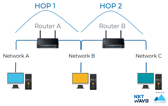
Hop
A hop occurs when a packet is passed from one network segment to the next.
Time to Live
The Time to Live or TTL indicates how many router hops a datagram can traverse before it reaches destination.


Transferring Data Over Network
The header (and footer) and the data together form the PDU for the next layer. The process continues until reaching the lowest-level layer (physical layer or network access layer), from which the data is transmitted to the receiving device. The receiving device reverses the process, de-encapsulating the data at each layer with the header and footer information directing the operations. Then the application finally uses the data. The process is continued until all data is transmitted and received.
